![[Prev]](/images/blue_prev.gif)
![[Next]](/images/blue_next.gif)
![[Contents]](/images/blue_toc.gif)
![[Commodore]](/images/blue_cbm.gif)
![[New]](/images/blue_new.gif)
![[Home]](/images/blue_home.gif)
It takes 2.56 to 2.62 usec to cancel the saddle. If the saddle should be longer than this length of time, the saddle can not be corrected and will result in a read error. Also, if the time for correcting the saddle is set for a longer time interval, the clear signal will not be set when the data is equal to 11. Therefore, approximately 2.6 usec the most suitable time setting for saddle correction.
Note: The minimum bit rate for tracks 1 - 17 is equal to 2.6 usec. If this time should become less due to motor speed, the SYNC signal cannot be recognized on the outer tracks resulting in error.
3. MOTOR SPEED COMPENSATOR (PLL)
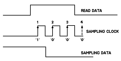
This gate array detects the motor speed and generates an internal data sampling clock signal that matches with the motor speed (see below).

When the SYNC signal goes to the low level, the LOCK signal goes false and the sampling clock is switched to the internal clock signal of the gate array. Once the PLL has sampled the data one's, the LOCK signal will go high to indicate that the output of the PLL is valid. If the PLL cannot lock on, the internal clock signal will be used and the LOCK signal will remain at the low level. This can occur when the stepper is still moving or the spindle motor is not up to speed yet. In short, this allows the reading of data independent of motor speed within the lock on limits of the PLL.

The 1571 runs on the SYSTEM CLOCK and does not implement the LOCK signal.
![[Prev]](/images/blue_prev.gif)
![[Next]](/images/blue_next.gif)
![[Contents]](/images/blue_toc.gif)
![[Commodore]](/images/blue_cbm.gif)
![[New]](/images/blue_new.gif)
![[Home]](/images/blue_home.gif)