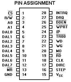
| PIN |
DESC |
DESC |
FUNCTION |
| 1 |
 | CHIP SELECT |
A logic low on this input selects the chip and enable
Host communication with the device. |
| 2 |
 |
READ/WRITE |
A logic high on this input controls the placement of data
on the D0-D7 lines from a selected register, while a logic
low causes a write operation to a seleeted register. |
| 3,4 |
A0,A1 |
ADDRESS 0,1 |
These two inputs select a register to Read/Write data:
 |
A1 |
A0 |
|
 =1 =1 |
 =0 =0 |
0
0
0
0 |
0
0
1
1 |
0
1
0
1 |
|
Status Reg
Track Reg
Sector Reg
Date Reg |
Command Reg
Track Reg
Sector Reg
Data Reg |
|
| 5-12 |
DAL0-DAL7 |
DATA ACCESS LINES 0 THRU 7 |
Eight bit bidirectional bus used for transfer of data, control, or status.
This bus is enabled by  and and
 . Each line will drive one TTL load. . Each line will drive one TTL load. |
| 13 |
 |
MASTER RESET |
A logic low pulse on this line resets the device
and initializes the status register (internal pull-up). |
| 14 |
GND |
GROUND | GROUND. |
| 15 |
Vcc |
POWER SUPPLY |
+5V ± 5% power supply input. |
| 16 |
STEP |
STEP |
The STEP output contains a pulse for each step of the
drive's R/W head. The WD 1770 and WD1772 offer different
step rates. |
| 17 |
DIRC |
DIRECTION |
The DIRECTION output is high when stepping in
towards the center of the diskette, and low when stepping out. |
| 18 |
CLK |
CLOCK |
This input requires a free-running 50% duty cycle clock
(for internal timing) at 8MHz ± 1%. |
| 19 |
 |
READ DATA |
This active low input is the raw data line containing
both clock and data pulses from the drive. |
| 20 |
MO |
MOTOR ON |
Active high output used to enable the spindle motor prior
to read, write or stepping operations. |
| 21 |
WG |
WRITE GATE |
This output is made valid prior to writing on the diskette. |
| 22 |
WD |
WRITE DATA |
FM or MFM clock and data pulses are placed
on this line to be written on the diskette. |
| 23 |
 |
TRACK00 |
This active low input informs the WD1770 that the drive's
R/W heads are positioned over Track Zero (internal pull-up). |
| 24 |
 |
INDEX PULSE |
This active low input informs the WD1770 when the physical Index
Hole has been encountered on the diskette (internal pull-up). |
| 25 |
 |
WRITE PROTECT |
This input is sampled whenever a
Write Command is received. A logic low on this line will prevent any Write Command from executing
(internal pull-up). |
| 26 |
 |
DOUBLE DENSITY ENABLE |
This input pin selects either single (FM) or double
(MFM) density. When  =0, double density is selected
(internal pull-up). =0, double density is selected
(internal pull-up). |
| 27 |
DRQ |
DATA REQUEST |
This active high output indicates that the data register
is full (on a READ) or empty (on a Write operation).
|
| 28 |
INTRQ |
INTERRUPT REQUEST |
This active high output is set at the completion of any
command or reset or read of the status register. |


 and
and
 . Each line will drive one TTL load.


 =0, double density is selected
(internal pull-up).
 =1
=1