WD1770 FLOPPY DISK CONTROLLER (CONTINUED)


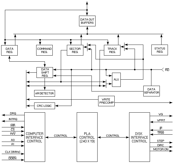
The Floppy Disk Controller block diagram is illustrated above. The primary sections include the parallel processor interface and the Floppy Disk Interface.
Data Shift Register — This 8-bit register assembles serial data from the Read Data input ( ) during Read operations and transfers serial data to the Write Data output during Write operations.
Data Register (DR) — This 8-bit register is used as a holding register during Disk Read and Write operations. In Disk Read operations, the assembled data byte is transferred in parallel to the Data Register from the Data Shift Register. In Disk Write operations, information is transferred in parallel from the Data Register to the Data Shift Register. When executing the Seek command, the Data Register holds the address of the desired Track position. This register is loaded from the DAL and gated onto the DAL under processor control.
Track Register (TR) — This 8-bit register holds the track number of the current Read/Write head position. It is incremented by one every time the head is stepped in and decremented by one when the head is stepped out (towards track 00). The contents of the register are compared with the recorded track number in the ID field during disk Read, Write, and Verify operations. The Track Register can be loaded from or transferred to the DAL. This Register should not be loaded when the device is busy.
Sector Register (SR) — This 8-bit register holds the address of the desired sector position. The contents of the register are compared with the recorded sector number in the ID field during disk Read or Write operations. The Sector Register contents can be loaded from or transferred to the DAL. This register should not be loaded when the device is busy.
Command Register (CR) — This 8-bit register holds the command presently being executed. This register should not be loaded when the device is busy unless the new command is a force interrupt. The command register can be loaded from the DAL, but not read onto the DAL.
Status Register (STR) — This 8-bit register holds device Status information. The meaning of the Status bits is a function of the type of command previously executed. This register can be read onto the DAL, but not loaded from the DAL.
CRC Logic — This logic is used to check or to generate the 16-bit Cyclic Redundancy Check (CRC). The polynomial is: G(x) = x16 + x2 + x5 + 1. The CRC includes all information starting with the address mark and up to the CRC characters. The CRC register is preset to ones prior to data being shifted through the circuit.